VENTILATION AIR
EXCHANGE CHART


Allegro Industries recommends
air exchange
at a rate of at least
20 times per hour.
CONFINED
SPACE
VOLUME
(CUBIT FEET)
BLOWER
CUBIC FEET PER
MIN. (CFM)
OUTPUT NEEDED*

1000 333

2000 667

3000 1000

4000 1333

5000 1667

6000 2000

7000 2333

8000 2667

9000 3000

10000 3333

*Take into account 90º bends of ducting.
See specifications under each blower
description.
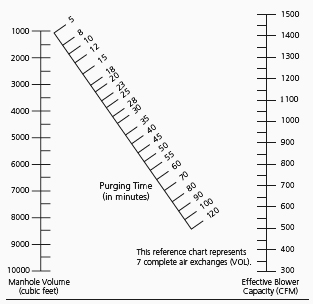
USE OF ALIGNMENT CHART
  1. Place straightedge on manhole volume (left scale).

  2. Place other end of straightedge on blower capacity (right scale).

  3. Read required purging time in minutes on diagonal scale.

  4. If two blowers are used, add the two capacities, then proceed as above.

  5. When toxic gases are encountered, increase purging time 50%.

  6. Effective blower capacity is measured with one or two 90º bends in standard 15-foot blower hose.
    See chart.
VENTILATION NOMOGRAPH
* HAZARDOUS LOCATION INFORMATION
Reference: Explosion Proof Blowers: 9503, 9515-01, 9513-05, 9514-05, 9514-06, 9509-01, 9538, 9538-15, 9538-25 and 9525-01* National Electrical Code (NEC) A hazardous location is an area where the possibility of explosion and fire is created by the presence of flammable gases, vapors, dusts, fibers or flyings.

NOTE: Fibers and flyings are not likely to be suspended in the air, but can collect around machinery or on lighting fixtures

and where heat, a spark or hot metal can ignite them.

CLASS I
CLASS II
CLASS III
(NEC-500-5)

Those areas in which flammable gases or vapors may be present in the air in sufficient quantities to be explosive or ignitable.

(NEC-500-6)

Those areas made hazardous by the presence of combustible dust.

(NEC-500-7)

Those areas in which there are easily ignitable fibers or flyings present, due to type of material being handled, stored, or processed.

DIVISION 1
DIVISION 2
GROUPS
(NEC-800-5, 6, 7)

In the normal situation, hazard would be expected to be present in everyday production operations or during frequent repair and maintenance activity.

(NEC-500-5, 6, 7)

In the abnormal situation, material is expected to be confined within closed containers or closed systems and will be present only through accidental rupture, breakage or unusual faulty operation.

(NEC-500-3)

The gases and vapors of Class I locations are broken into four groups by the code: A, B, C, and D. These materials are grouped according to the ignition temperature of the substance, its explosion pressure and other flammable characteristics.

The dust locations of Class II are designated E, F, and G. These groups are classified according to the ignition temperature and the conductivity of the hazardous substance.

NOTE: For detailed group descriptions refer to NEC-500-3.

TYPICAL CLASS I LOCATIONS
TYPICAL CLASS II LOCATIONS
TYPICAL CLASS III LOCATIONS
  • Petroleum refineries, and gasoline storage and dispensing areas.
  • Industrial firms that use flammable liquids in dip tanks for parts cleaning or other operations.
  • Petrochemical companies that manufacture chemicals from gas and oil.
  • Dry cleaning plants where vapors from cleaning fluids can be present.
  • Companies that have spraying areas where they coat product with paint or plastics.
  • Aircraft hangers and fuel servicing areas.
  • Utility gas plants, and operations involving storage and handling or liquefied petroleum gas or natural gas.
  • Grain elevators, flour and feed mills.
  • Plants that manufacture, use or store magnesium or aluminum powders.
  • Plants that have chemical or metallurgical processes, producers of plastics, medicines, and fireworks, etc.
  • Producers of starch or candies.
  • Spice-grinding plants, sugar plants and cocoa plants.
  • Coal preparation plants and other carbon-handling or processing areas.
  • Textile mills, cotton gins, cotton seed mills and flax processing plants.
  • Any plant that shapes, pulverizes or cuts wood and creates sawdust or flyings.
** WARNING: Explosion-proof blowers must be used with statically conductive ducting.